STORMWATER MANAGEMENT REPORT
Prepared for: I. Introduction
The project consists of an expansion of an existing parking lot as shown on the site plan, Since
the proposed parking lot expansion exceeds the ¼ acre threshold for new impervious cover
(NJDEP - BMP manual), a stormwater management system (SMS) will be proposed for the site.
The project is located adjacent to a residential neighborhood off of Blair Road. The offsite area
to the north of this site contains an existing stormwater management pond that serves the existing
site and some of the surrounding offsite areas. The current drainage from the existing site is
collected and delivered to that pond through the use of a stormwater pipe and overland flow.
Since the existing pond is unavailable for the parking lot expansion, an additional system is
being proposed and analyzed in this report. This section will consist of a sealed underground
(oversized) storm sewer and a downstream water quality device provided by Contech Engineered
Solutions (Model CDS-8-C/see plans).
II. Design Standards
The BMP manual promulgated by NJDEP requires the following design standards:
1. Flowrate and Volumetric control of 2, 10 and 100 year for the increased impervious area.
2. Water Quality (WQ) treatment for the WQ storm.
3. Groundwater recharge of the existing runoff.
The design of a system to meet the abovementioned requirements can be accomplished by
many methods as outlined in the BMP manual. Normally a site engineer would propose a surface
infiltration pond for such a site if physical conditions allowed for such a facility. The western
side of the site will not have enough surface area to provide for a surface storage/infiltration
volume. In addition, the amount of increased flow is a relatively small number especially
compared to the rest of the existing site. Furthermore, a subsurface soil investigation performed
on March 1, 2017 (witnessed by a representative of CME Associates) indicated a sandy loam soil
with mottling from the 2 to the 10 foot depth in all of the 3 test pits. One of the soil logs (#2) had
water entering the test pit at the 2 foot depth. A permeability rating* of the soil samples was
performed by Key-Tech and indicated a relatively low permeability for soils typically found in
Monmouth County, (See appendix/plans for soil log data/location and the lab results).
*Not used for design purposes III. Design Proposal
site.
Based upon the above the following stormwater management system is proposed for this
1. An underground, sealed stormwater pipe that will provide flowrate and volume control for
the increased impervious area. This proposal will not have a subsurface disposal
(infiltration) system because of the poor soil conditions. Therefore, the required two-foot
separation from the seasonally high groundwater table is not a factor in the proposed design.
2. Provide a WQ control device downstream of the control structure for 1 above (Contech).
3. The Monmouth County Soil Survey Maps indicate a D soil at this site which will not be
effective for groundwater recharge. Since groundwater recharge on the site will not
be successful for the reasons outlined in II above, it is proposed that this requirement will be
indirectly met by utilizing the existing off-site pond for this purpose. The effectiveness of
any other on-site system for groundwater recharge is highly questionable. The calculations
shown in the Appendix of this report analyzes the proposed system.
IV. Conclusions
The analysis contained in this report demonstrates that the SMS has been designed to meet
current stormwater regulations. The reduction in flow from the proposed parking area to
values less than existing conditions precludes any further analysis of offsite, downstream
stormwater facilities.
Design Note
The analysis of the outflow hydraulics for the control structure does take into account a
tailwater elevation by utilizing ASCE partial element diagram (see page 3 of the appendix).
This tailwater elevation (34.2) was manually entered into the routing program (see page 11). APPENDIX FRONT
OF
THE
(SEE
SITE PLAN
TAB RAM os
LOT 6 BL 12
1. PROJECT
DESCRIPTION
THE PROJECT CONSISTS
AN EXISTING
ABERDEEN, N.J. 1
9/5/17 3/1/17
5/2/17
7/11/17
OF EXPANDINL
LOT IN
BUILDING
CONSTRUCTION
PARKING
CURRENT
THIS
WILL
INCREASE
THE
IMPER Vious
AREA
A
IS
FOR
BY 15, 470 ft² C0.355 AC)
STORMWATER
PROPOSED
MANAGEMENT
SYSTEM
WESTERN SIDE
Of THE SITE
N
2,
CRITERIA/DATA
3.
DESIGN
ABERDEEN TWSP
ENG.
STANDARDS
NJ DEP
MANUAL
(REFERENCE)
STORMWATER
MANAGEMENT SYSTEM (SMS)
CONSIST OF
THE
SMS
WILL
AN
UNDERGROUND
STORAGE
CONDUIT
LOCATED
NEW
PAVEMENT AREA
UNDER
AS
THE
SHOWN
ON
THE
SITE
PERFORMED
AT
PLAN.
THE
SOIL TESTIN
SMS
INDICATES
A
(SEE
SOIL
5012
MAPS
CHYDROLOGICAL
HIGHLY IM PERMEABLE
LAB REPORTS/KEY TECH AND
LOG LOCATIONS).
SOIL (KemB) FOR THIS
SCS
KEYPORT
RATING D). THIS MAP
SOILS.
THE
INDICATE
FURTHER VERIFIES
A
SITE
THE FIELD
OBSERVATIONS.
4
DESIGN
HYDROLOGY
*
Q..
DRAINAGE
AREA =
15,470 ft² (0.355A)
вра
SOIL
TYPE
D
STORAGE
ONLY
SCS
турт
di
RCN = 80 CEXISTING), 98 (PARKING LOT)
* INCREASED
IMP, AREA
STORM/n ◄ Outlook
1:24
23:26
Olenik, Thomas J's desktop
и
QCamera
Layout
.II 5G
&
POND
роите
THROUGH
DOES
XX EXIST
ELEV
Q DEV
THE
VS VOL VS DISCHAR
HYDROG.
LEAVING POND
POND
LESS
THAN
Q EX
PEAK?
Enter
IF
NOT
RAISE
POND VOL
+1OR
ENG
REPORT
ADJUST CONTROL STRUCT.
MAYI NOON DEADLINE
No
CRYING
1:24 PM
82°F Mostly sunny
4/25/2024
Olenik, Thomas J: It is May third at eight thirty a.
m.
eight two oh five K.
Q
<» 1:27
◄ Messages
33:43
Olenik, Thomas J's desktop
и
QCamera
Layout
&
CE
321
PROJECT STATUS
COMPLETED
GRADING
PLAN
STORM
SEWER
INVERT
ELEK
و
Layout
DESIGN STORM SEWERS
MAKE
SENSE
POND: ELEV VS. VOL
NEXT
Sum
Q DEV
HYDROGRAPHS
EXIST
C
1:27 PM
VIX -4.25%
4/23/2024
the stormstore is done by the software, and then
this is the key hard question
Q
B 1:46
52:26
Olenik, Thomas J's desktop
и
Layout
&
QCamera
WEIR
99.5
QLEAVING
C
ELEV. 97
= Q 3" +Q12" + QUEIR
← 20 cfs,
1:46 PM
VIX -4.60%
4/23/2024
Olenik, Thomas J: All of it has to be less than or
equal to twenty CFS, which was our que existing.
Q
B
口 1:05
08:02
Olenik, Thomas J's desktop
Layout
и
... LTE
&
QCamera
109
4-1
PIPE
1
Son
INV
TOP
OF INLET CIVIL
INV. 106.05
L= 200 ft
So₁
INV 105.10
INV105.00
>
I-2
105.10.
PIPE
INVI-3
PIPE
3
105.60
Son
DATA
INVERT
100.68
POND
3D
(BOTTOM
ELEV
STREAM
INVERT.
94.36
HEADWALL 98) CONTROL
STRUCT
% PIPE INVERTS
2.
PIPE LENGTHS
So
3. COMPUTE
PIPE 1
EX:
4. MAKE
STICK
5.
FOR
EACH PIPE
So = 106,05 -105.10 = 0.00475
SURE
out
200 ft
PIPES
DO
NOT
OF
THE GROUND/COVER
DETERMINE D. A. FOR EACH
INLET BASED
UPON
GRADED
SAME
FOR
Tc, C
Q0+ Q
MAP
1:05 PM
66°F Cloudy
4
4/11/2024
Olenik, Thomas J: And of course the key thing is
the slopes of your pipe because that'
Q
<»> 1:06 1
ClockShark
yahoo!
n
QCamera
EWERS
2
414
EN.
EAM.
A
... LTE
Credit Card Invitation
now
pankaj0974@yahoo.com, Apply NOW - $700...
COMPUTE/RUN
7.
USE
COMMANDS
8.
TO
SIZE/DESIGN
PIPES (WILL GIVE You PIPE
SIZE, PLAN, AND PROFILES)
DOES HT MAKE SENSE?
POND
DESIGN
STORMWATER
MANAGEMENT
1:06 PM
Temps to drop
4
4/11/2024
the compute run command and that the computer
will, the software will
Q
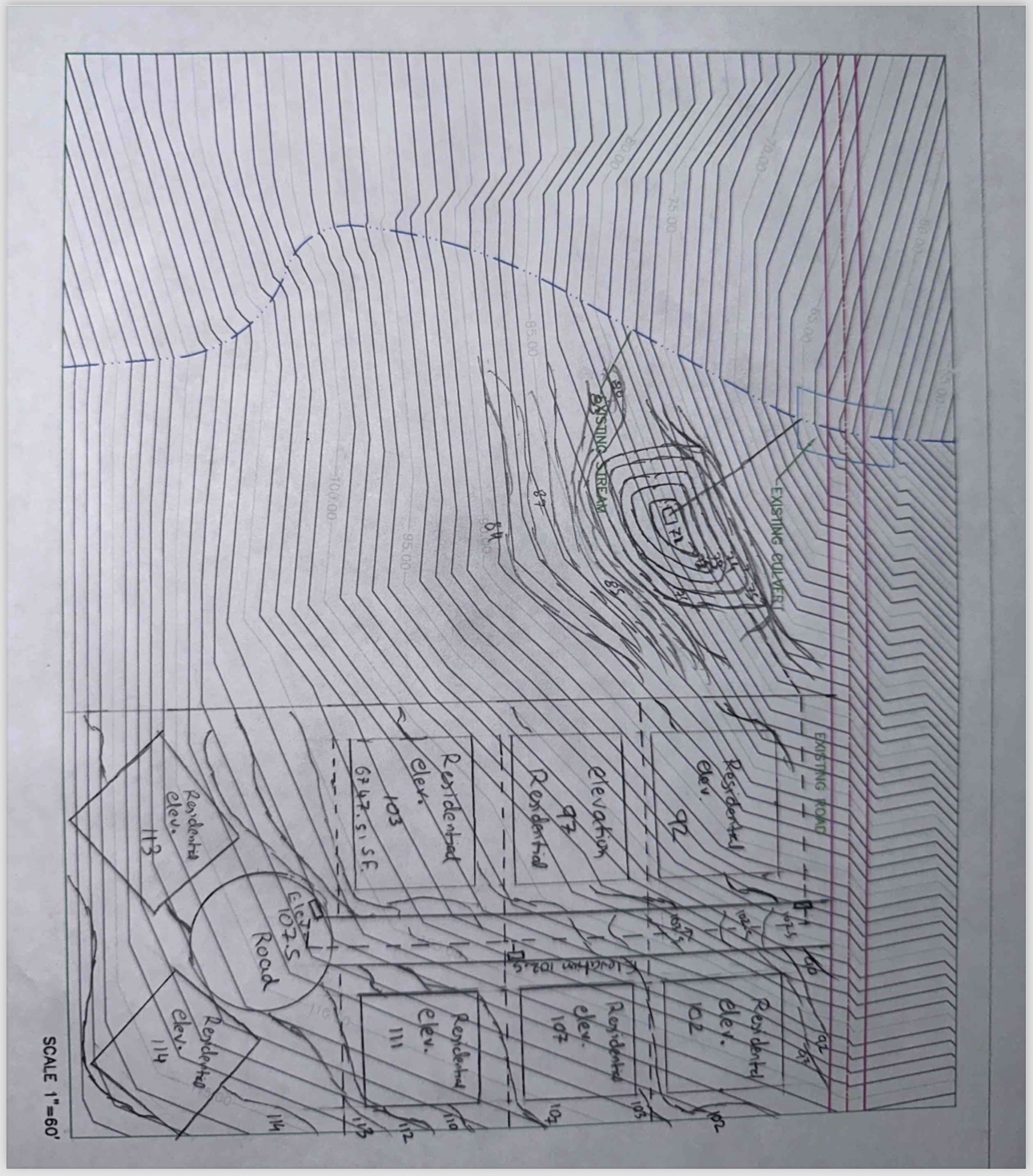
<»/n-80.00-
75.00-
5.00
EXISTING CULVERT
85.00
EXISTING STREAM
87
100.00-
95.00-
EXISTING ROAD
702
Residental
elev.
92
elevation
Az
Residential
Rex denta
eley.
102
Residenti
exey
107
103
102
Residential
elev
103
6747.51 SF
Residential
elev
111
119
Residenti
elev
113
Ele
T075
Road
Residential
elev
114
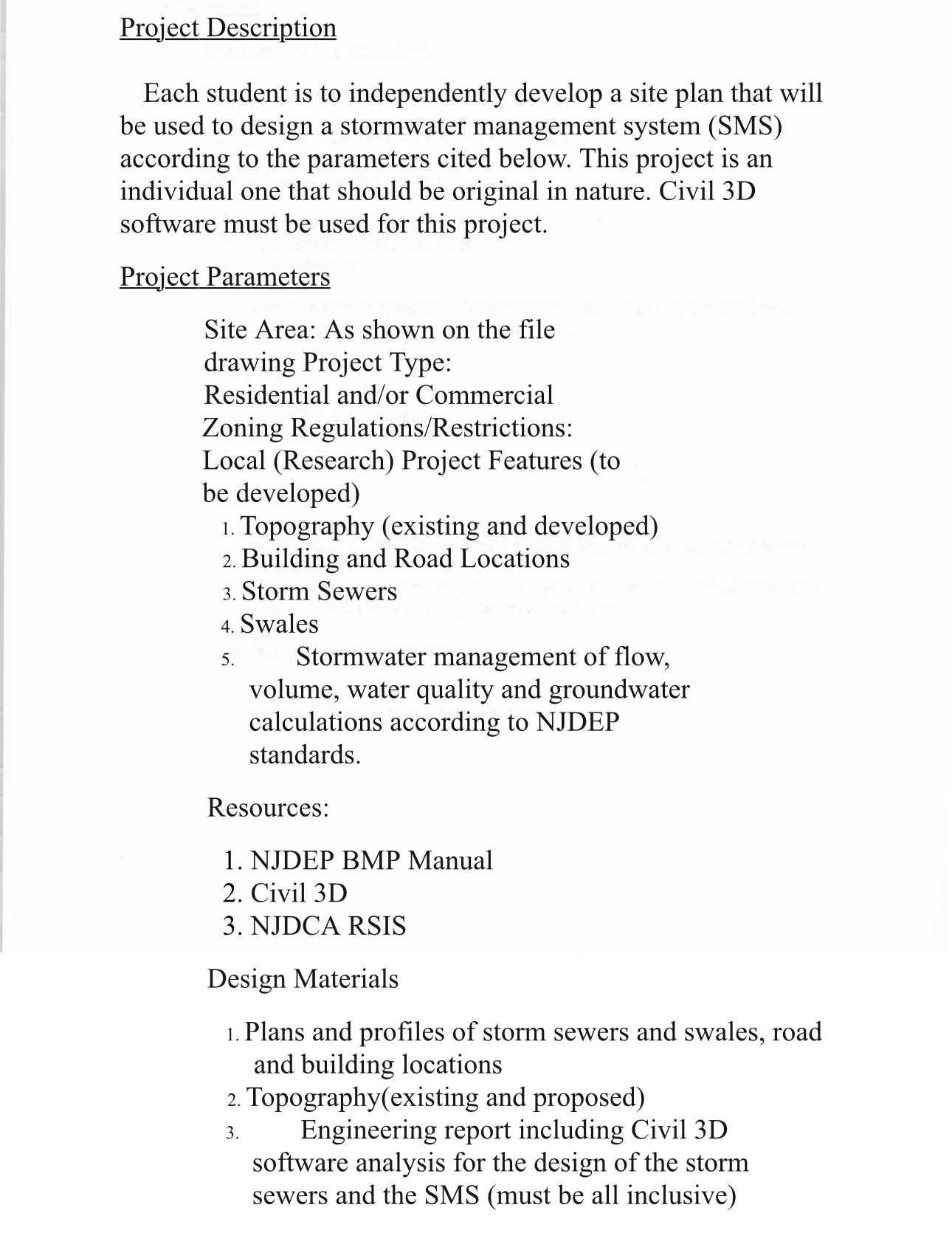
SCALE 1"-60'/nProject Description
Each student is to independently develop a site plan that will
be used to design a stormwater management system (SMS)
according to the parameters cited below. This project is an
individual one that should be original in nature. Civil 3D
software must be used for this project.
Project Parameters
Site Area: As shown on the file
drawing Project Type:
Residential and/or Commercial
Zoning Regulations/Restrictions:
Local (Research) Project Features (to
be developed)
1. Topography (existing and developed)
2. Building and Road Locations
3. Storm Sewers
4. Swales
5. Stormwater management of flow,
volume, water quality and groundwater
calculations according to NJDEP
standards.
Resources:
1. NJDEP BMP Manual
2. Civil 3D
3. NJDCA RSIS
Design Materials
1. Plans and profiles of storm sewers and swales, road
and building locations
2. Topography(existing and proposed)
3.
Engineering report including Civil 3D
software analysis for the design of the storm
sewers and the SMS (must be all inclusive)